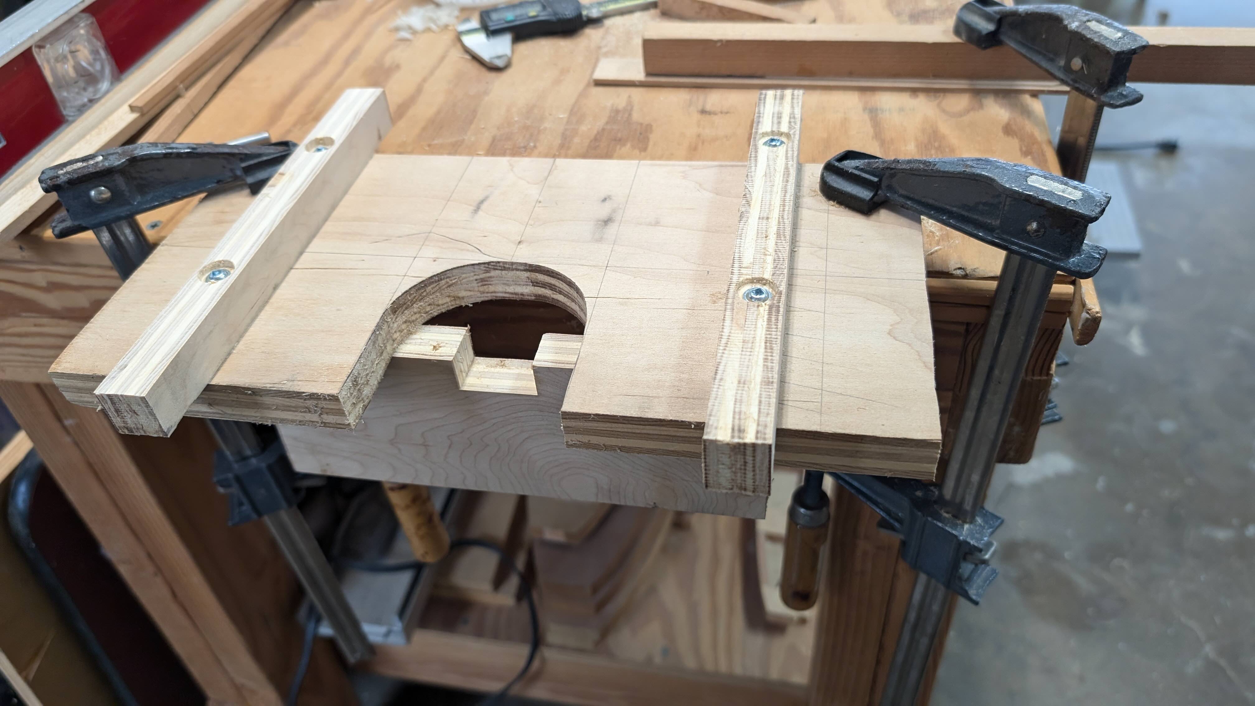
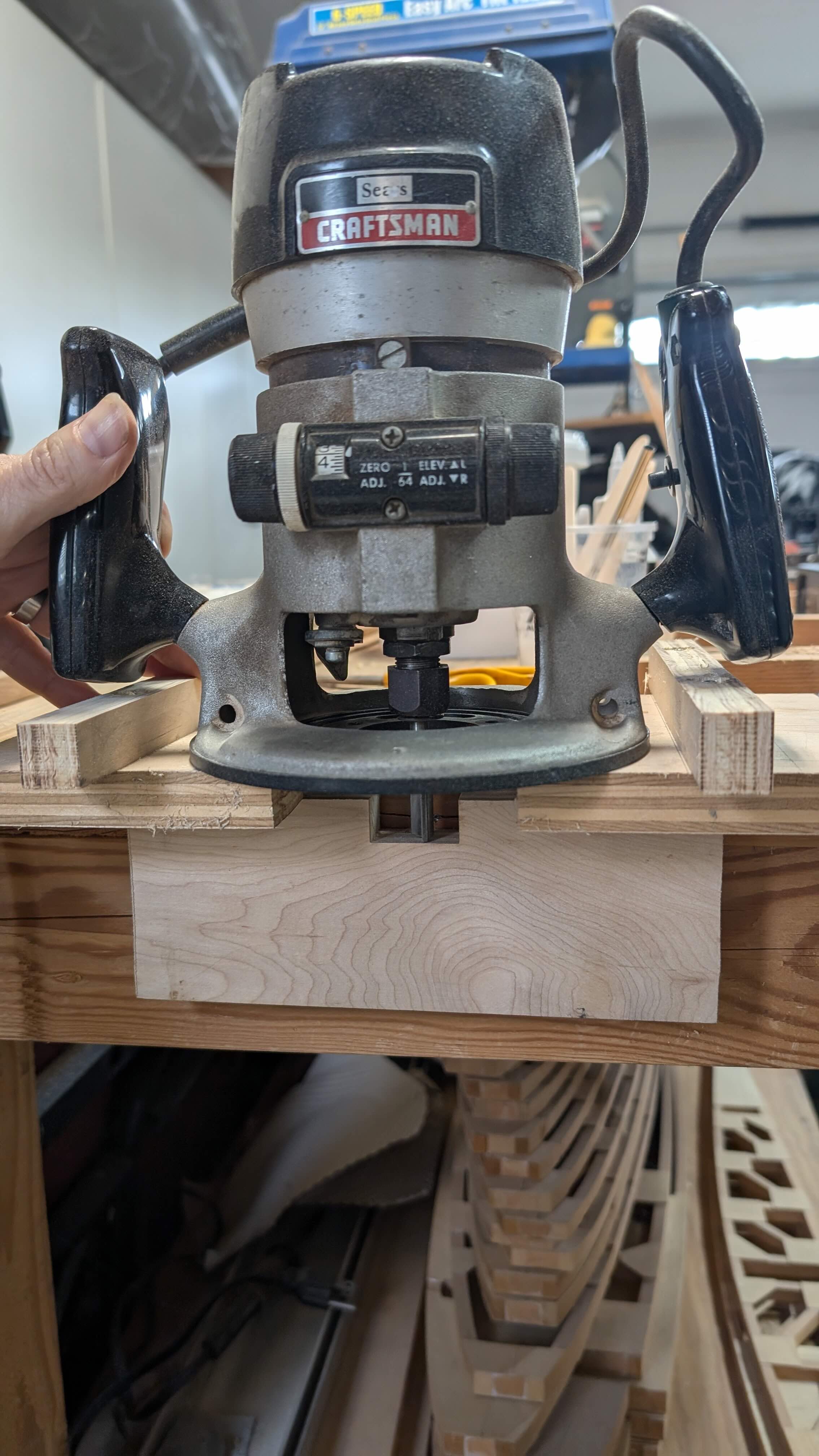
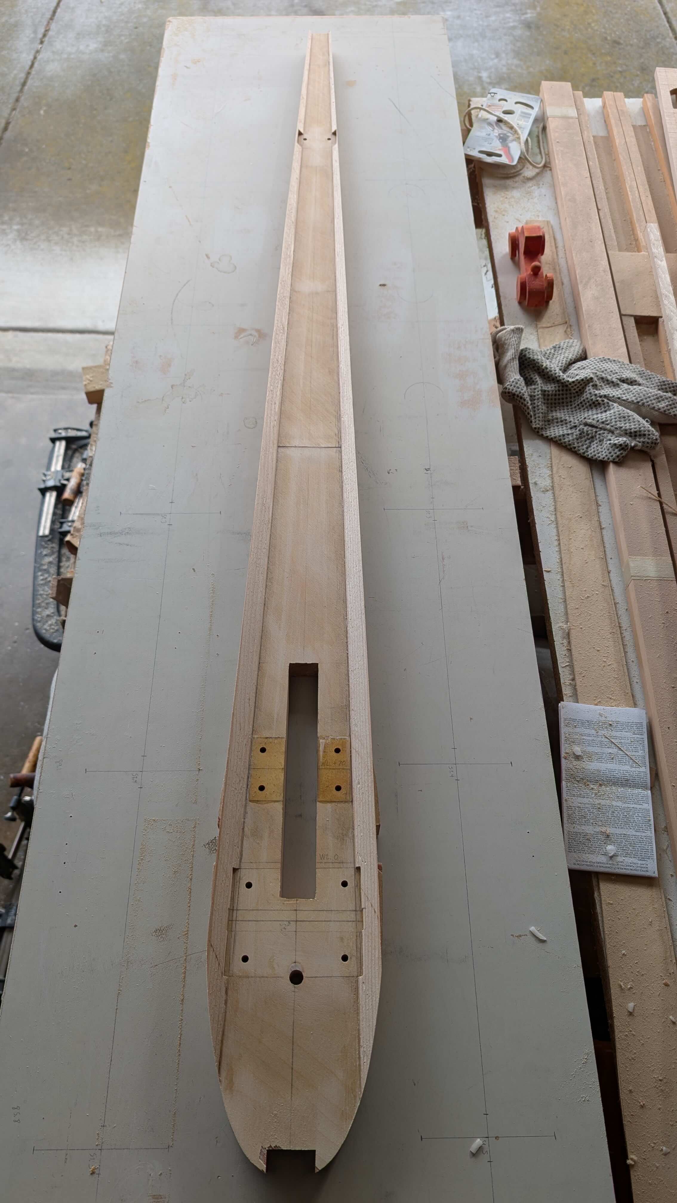
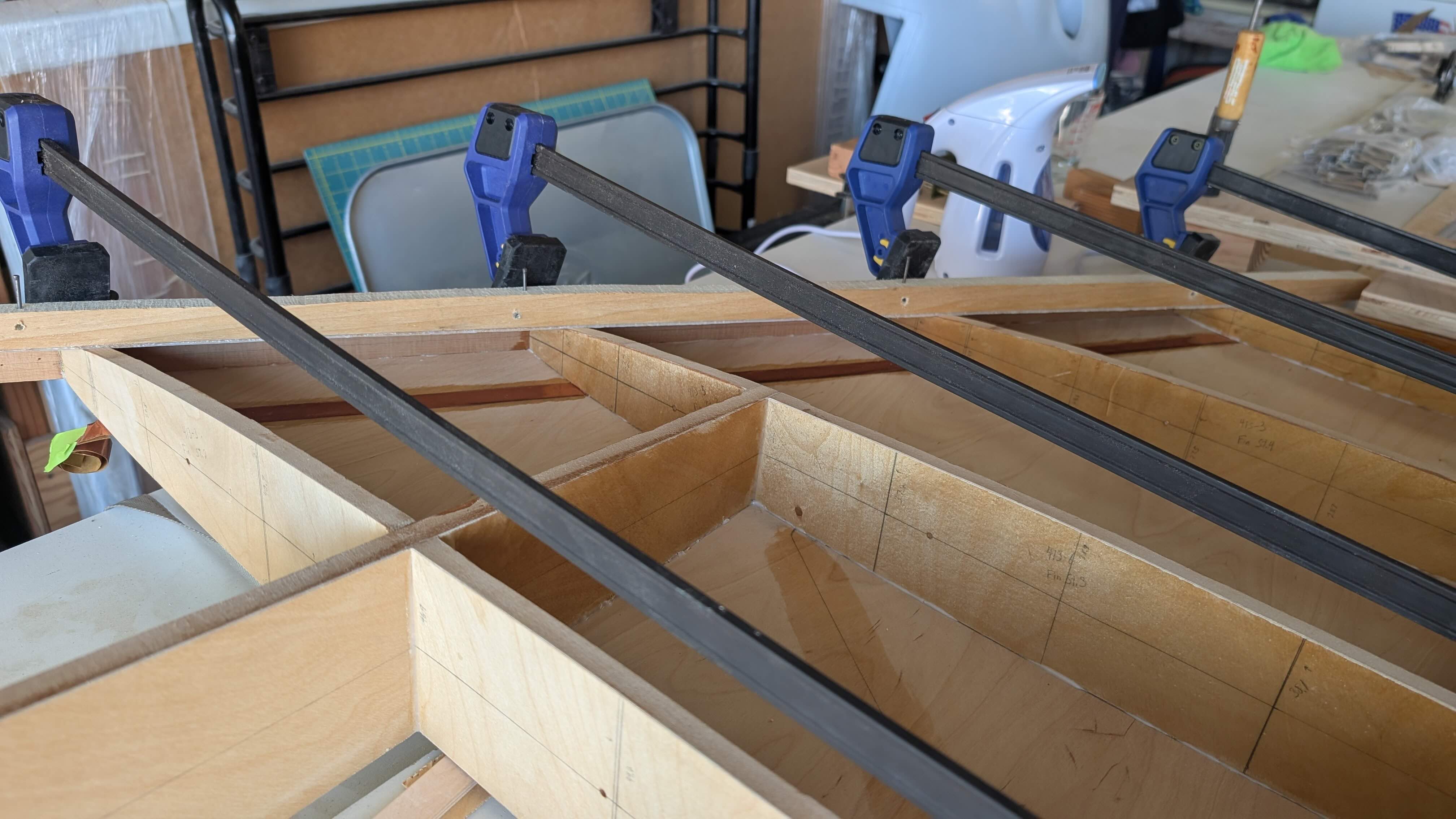
The first order of business was to make some cutouts in the fin spars for the longerons that connect the fuselage frames together, since the fin spars are also the last two aft fuselage frames. I made a jig to accurately make these cuts with my (well aged) router.
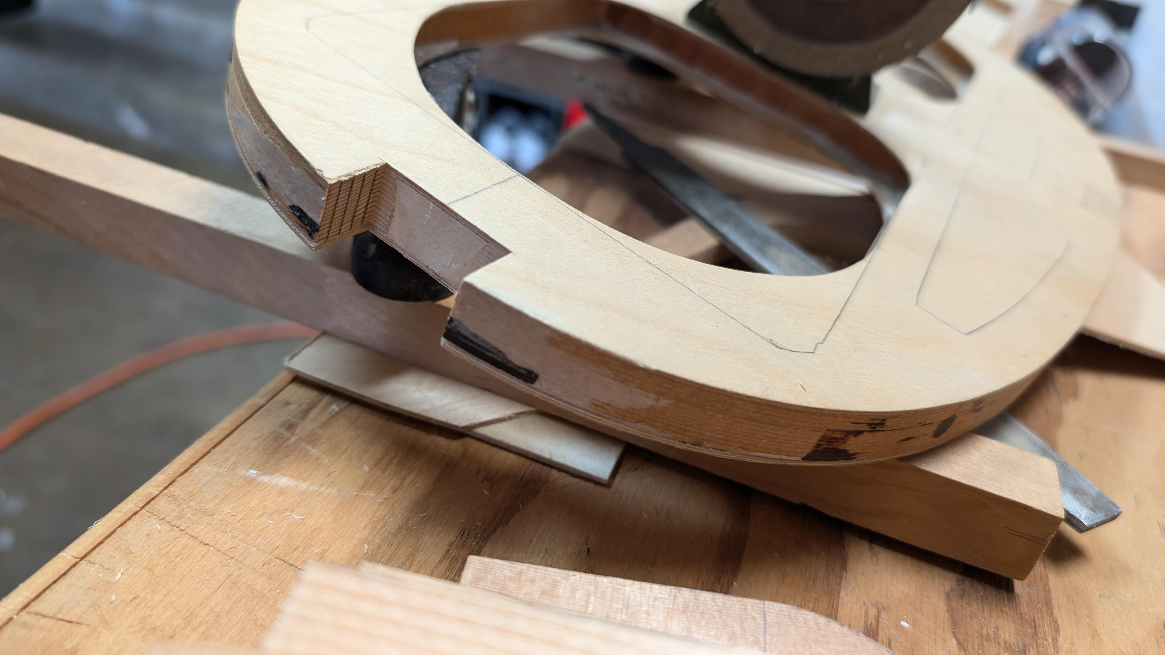
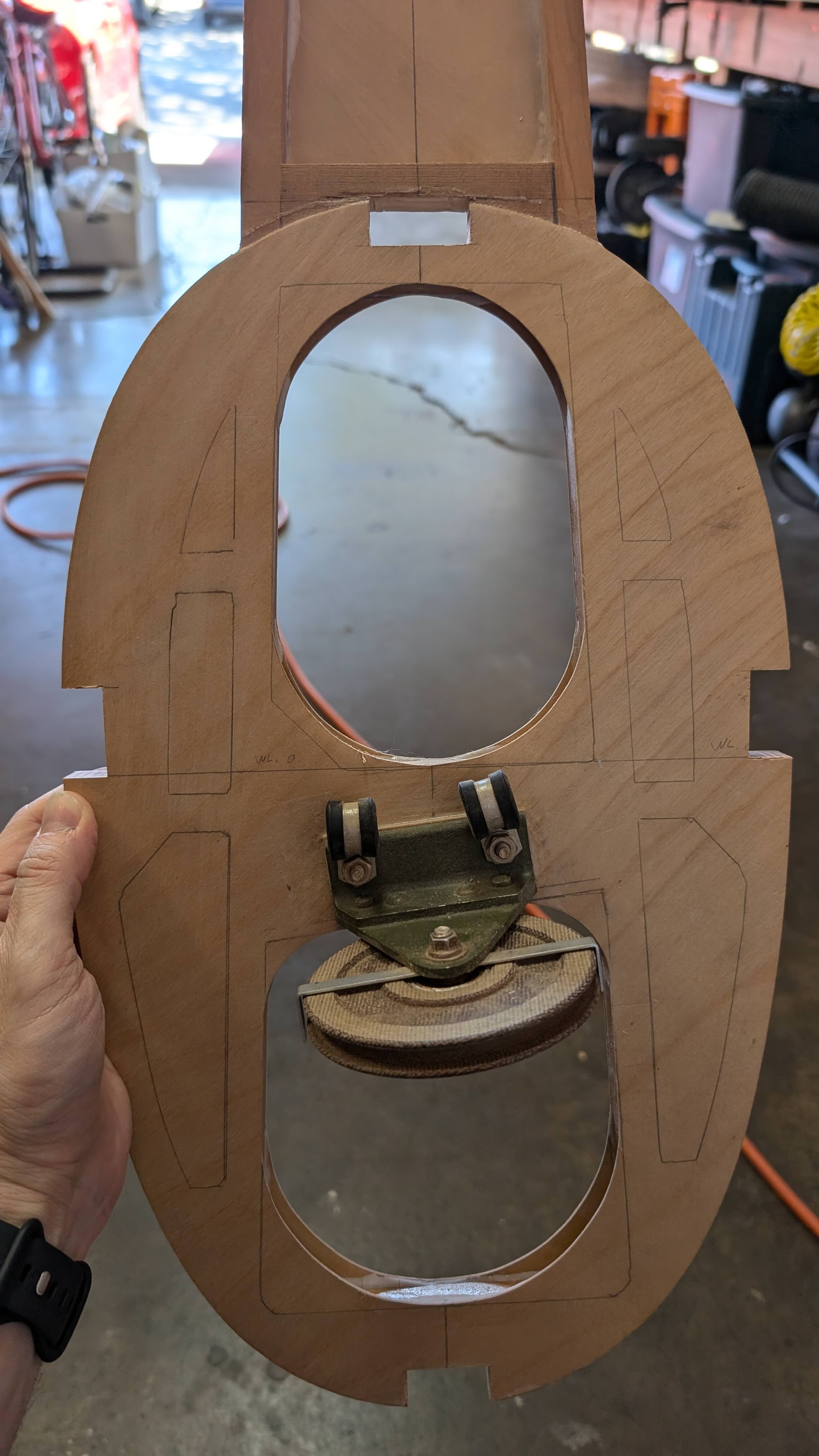
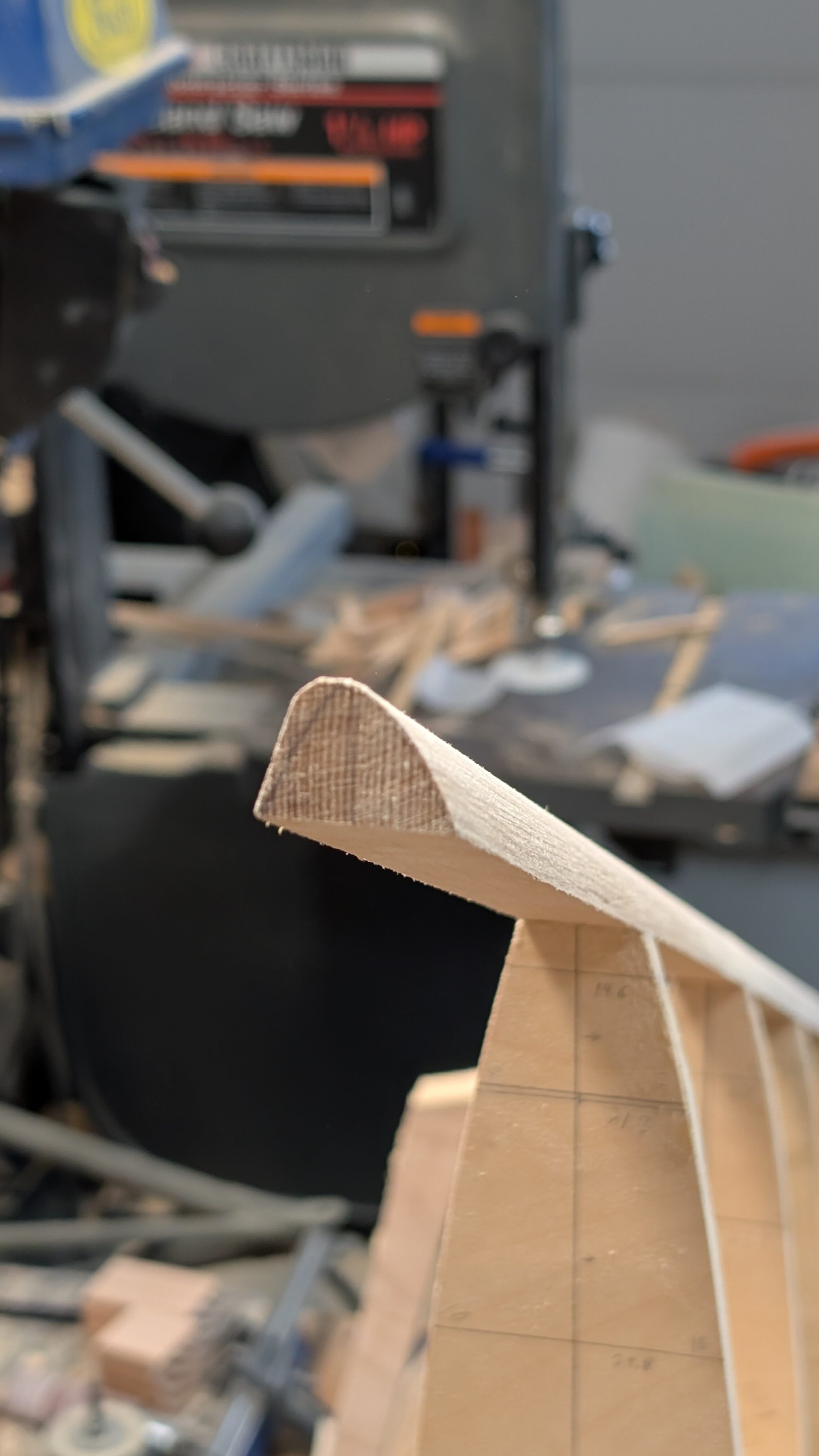
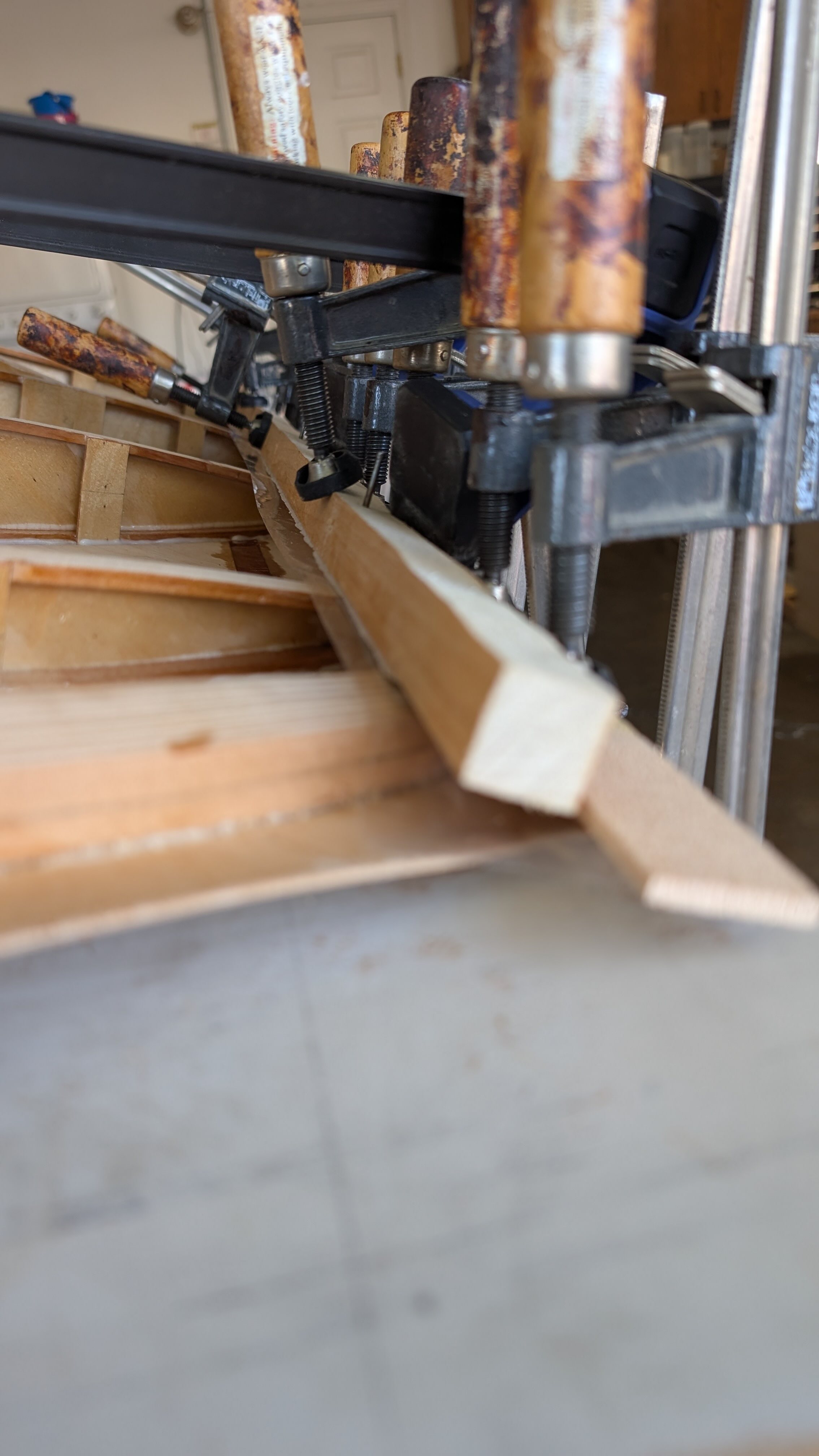
I made the triangular fairing strips that are attached to the aft face of the main fin spar and notched them for the hinges. After gluing them on, I trimmed them to match the spar.
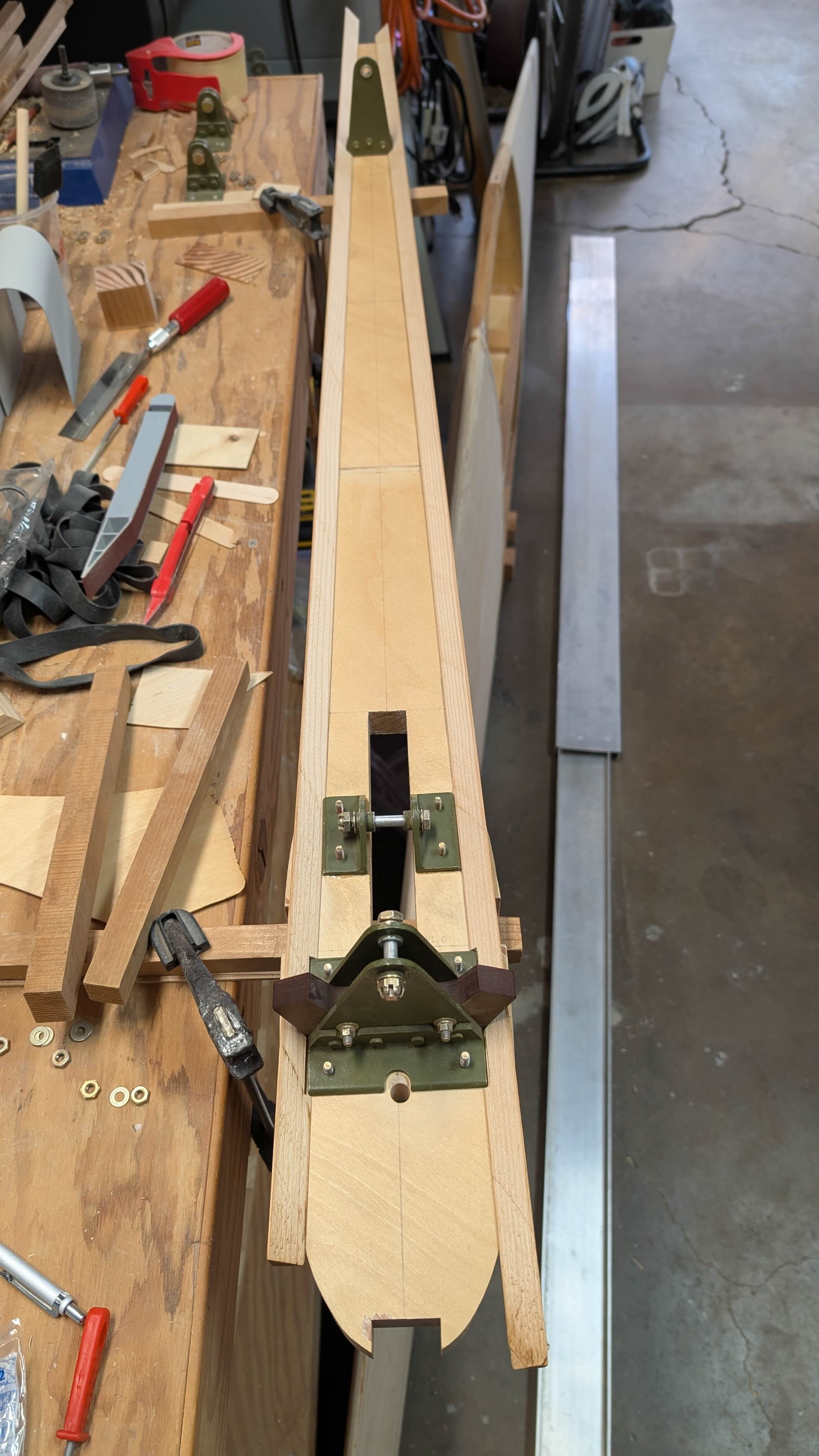
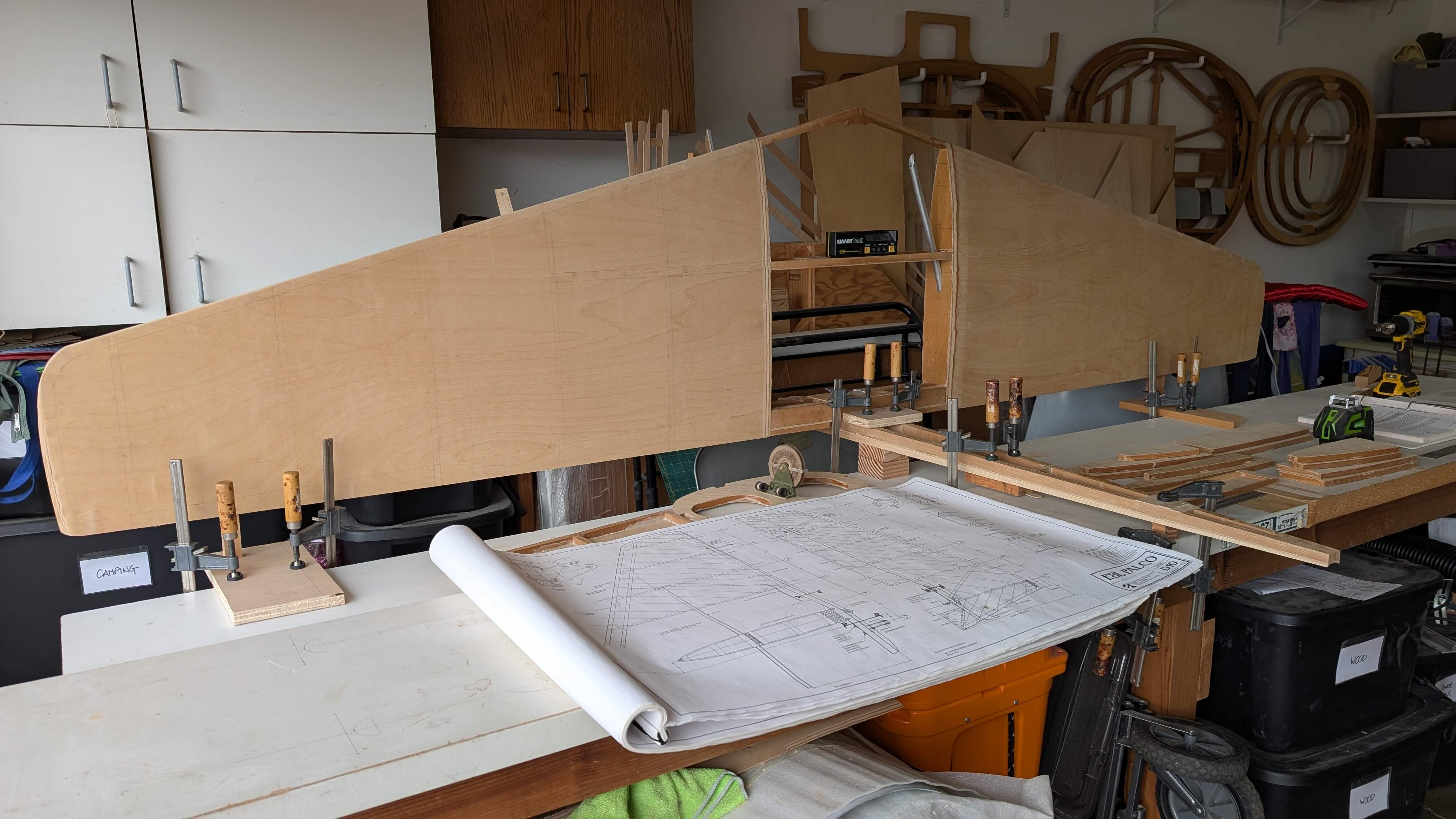
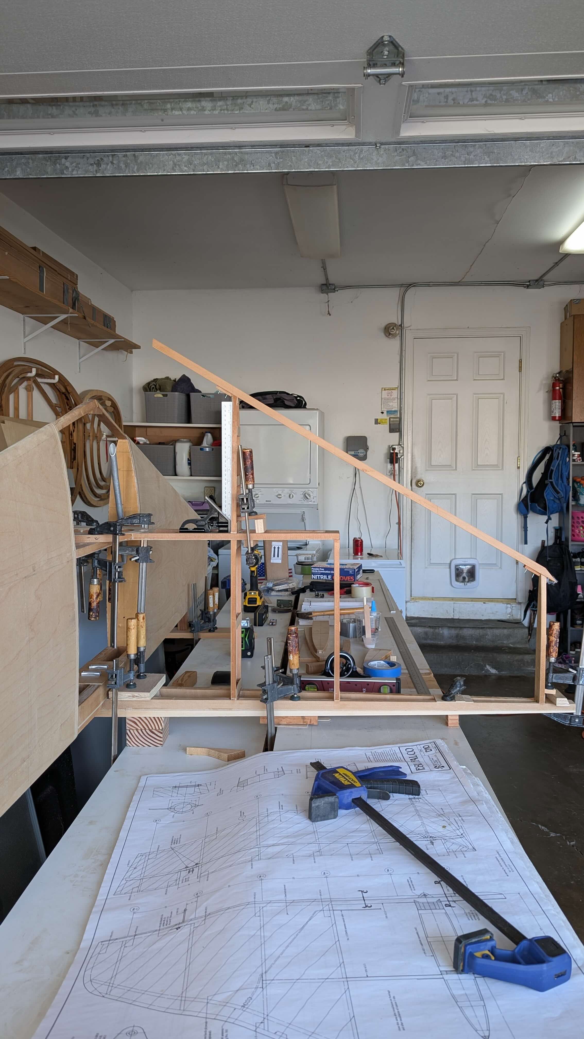
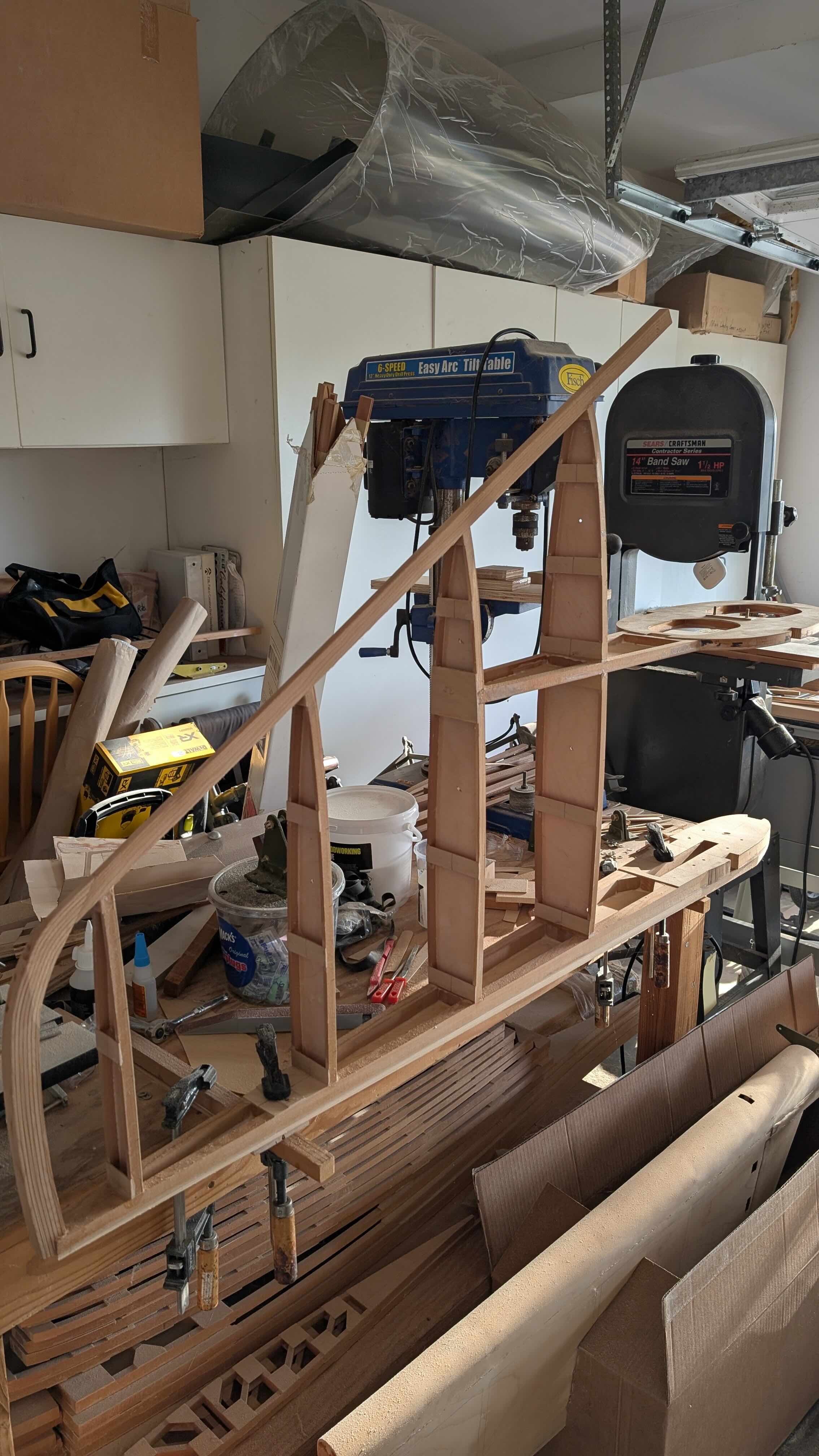
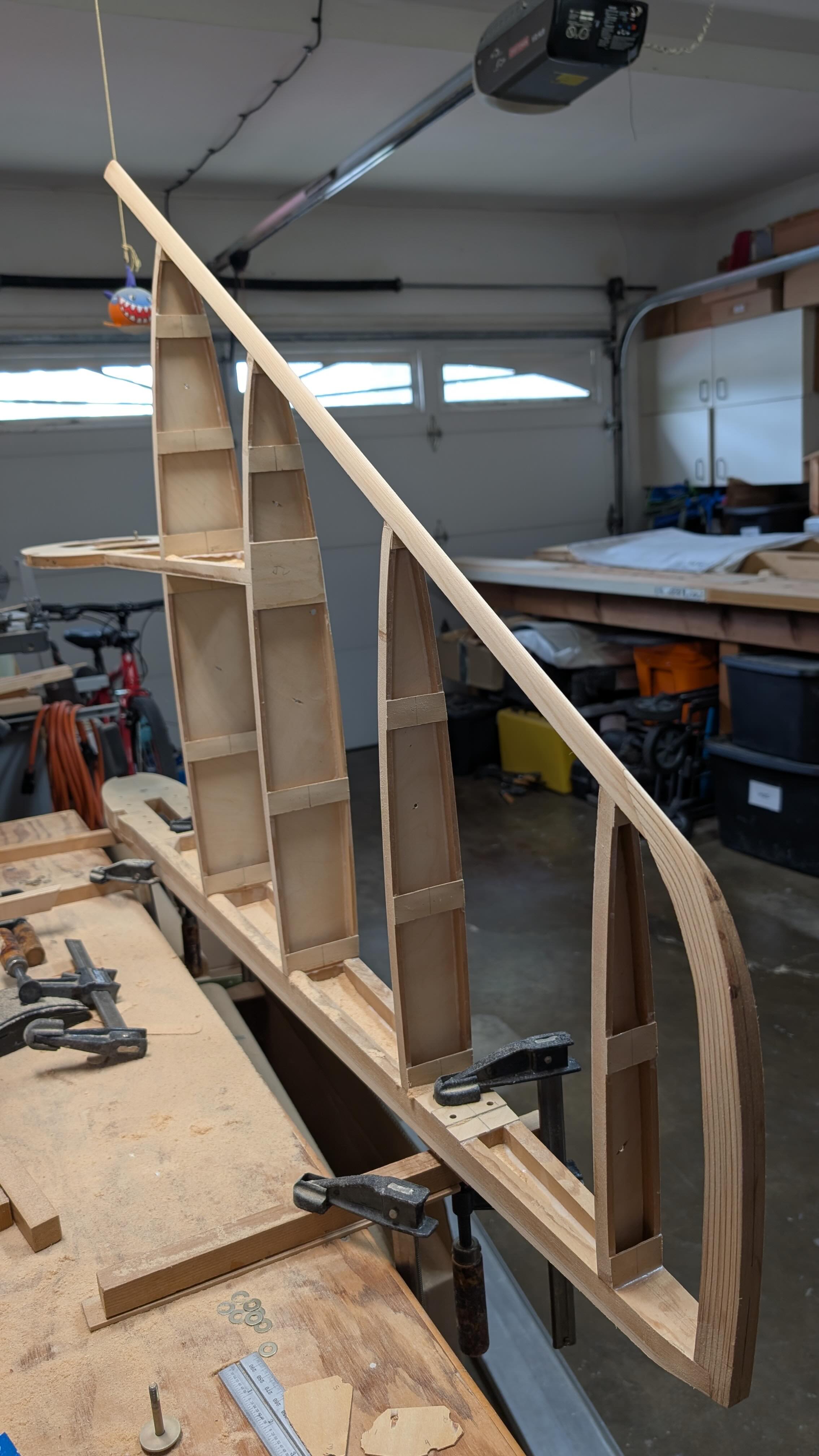
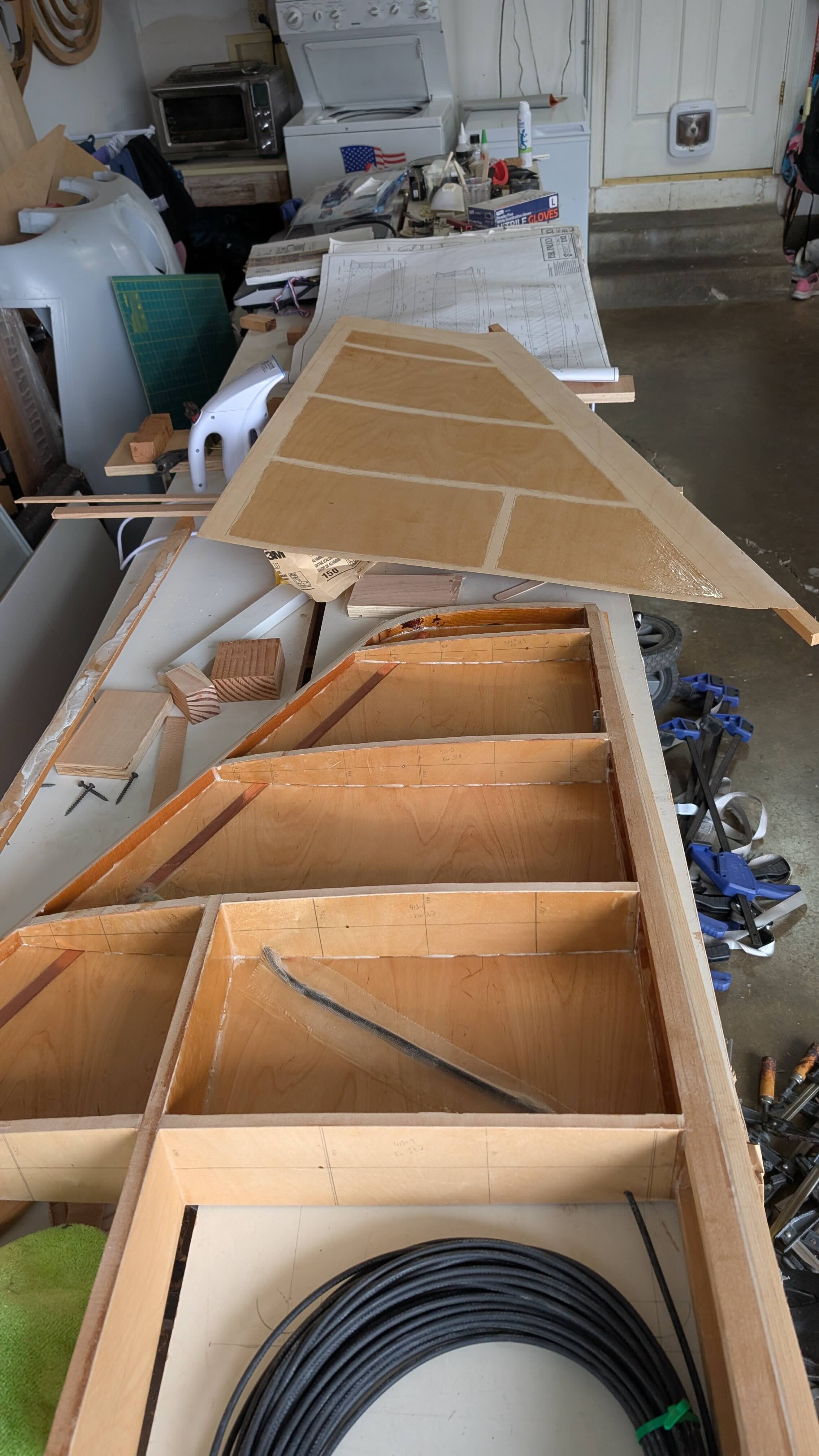
Since the distance between the two fin spars and the alignment of the vertical fin with the main fuselage is set by its attachment to the horizontal stabilizer, the fin is built while being carefully aligned with the completed horizontal stabilizer. I set up this arrangement along my worktable, supporting the structure as necessary and allowing room for clamps needed to build the fin structure. I double, triple and quadruple checked the level and alignment of the various spars throughout the build of the fin structure. This alignment was also maintained by the hinge bolt holes that were matched drilled through the main stabilizer and main fin spar oh-so-many years ago. May 17, 2008
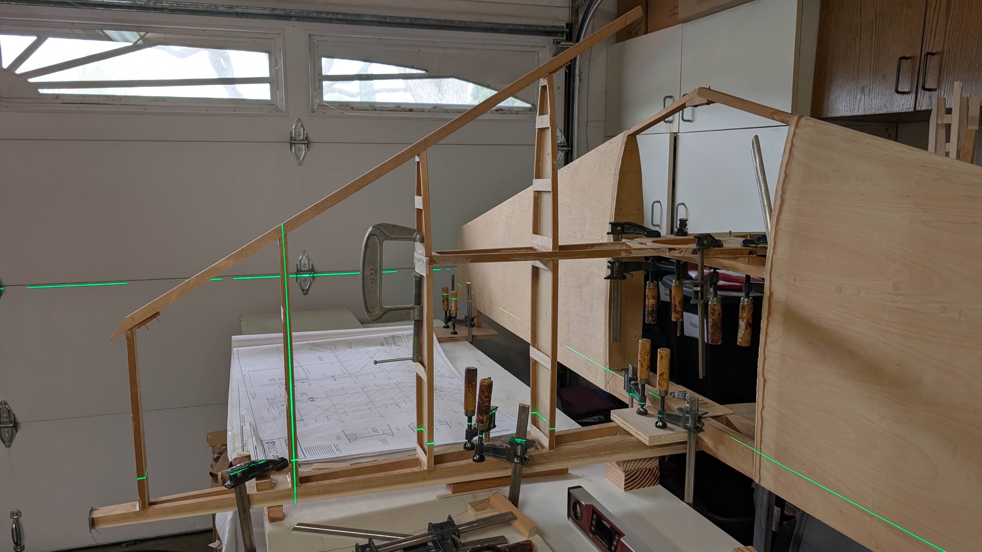
The first ribs go on and the forward fin spar, keeping things aligned, plumb and level with thread and the laser level.
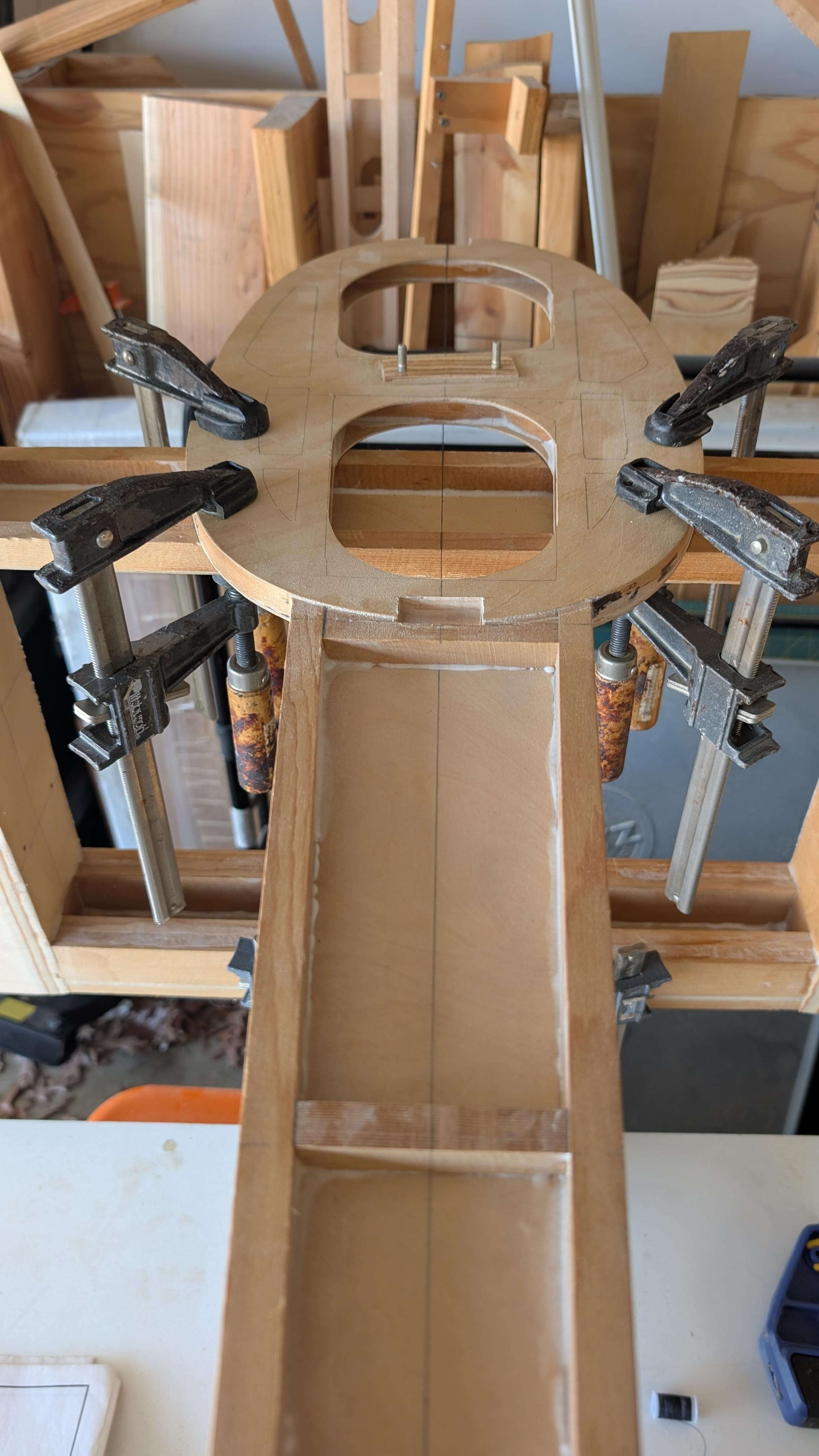

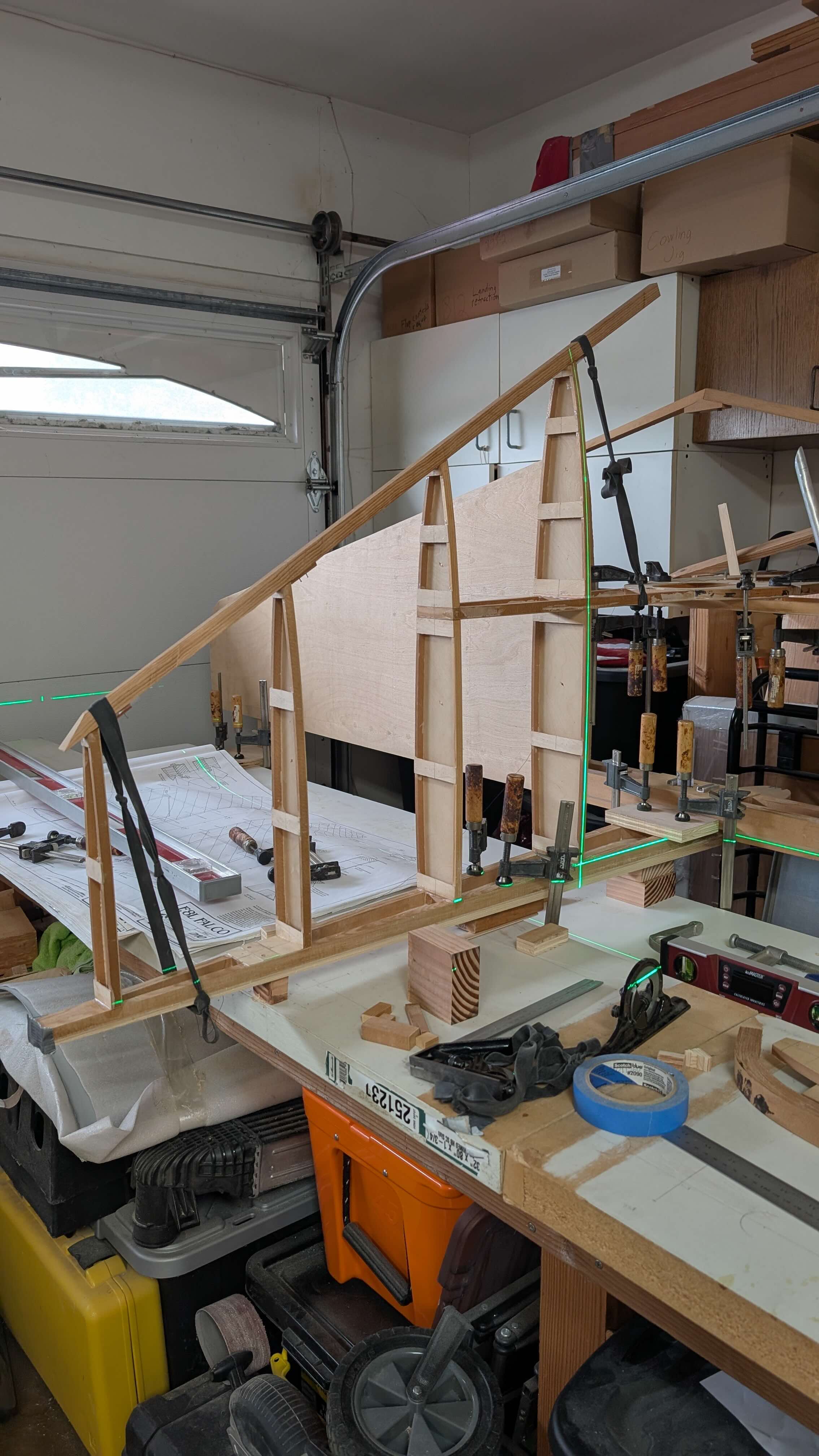
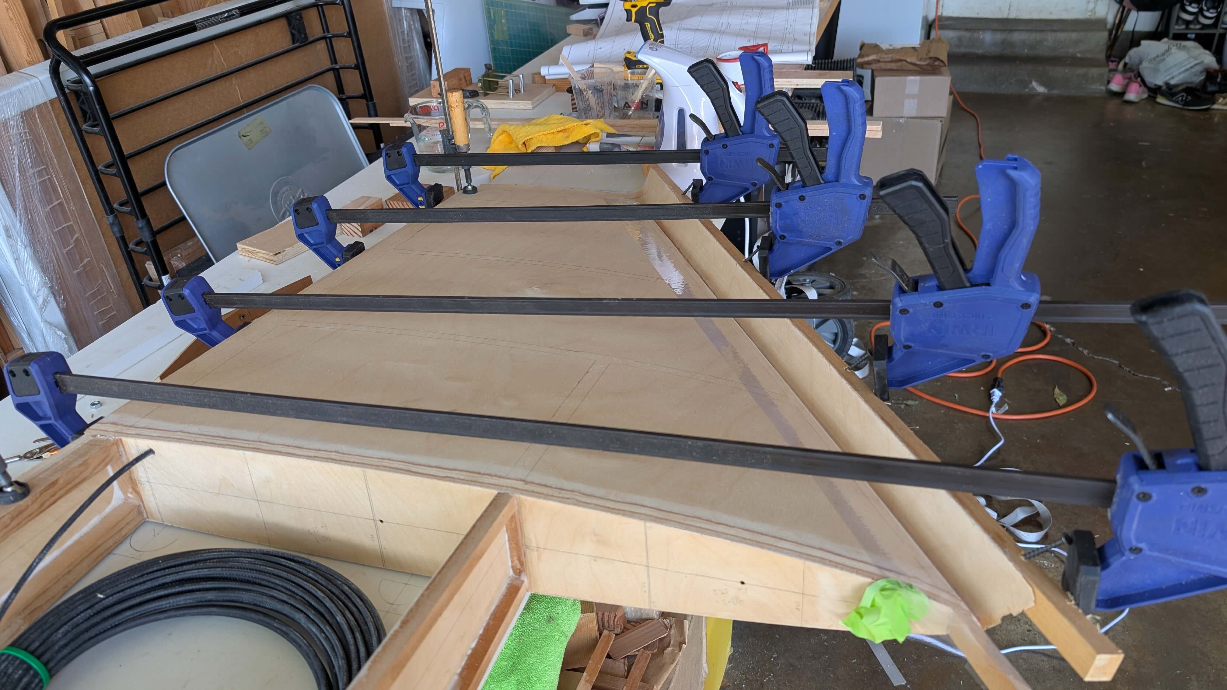
Leading edge ribs go on with alignment assistance from a square and the leading edge strip.
Final ribs glued on, then the leading edge strip, keeping alignment with the laser level. The leading edge strip is kept from sliding with the little blocks temporarily nailed to the underside.
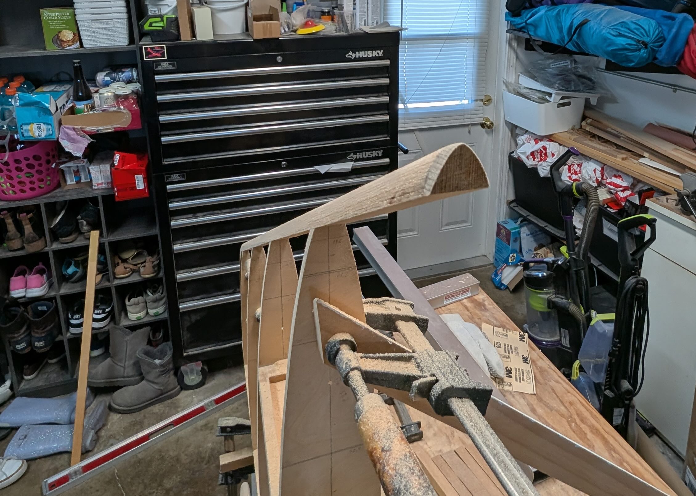
And to complete the structure, the laminated fin tip was glued on after many hours of pre-shaping it.
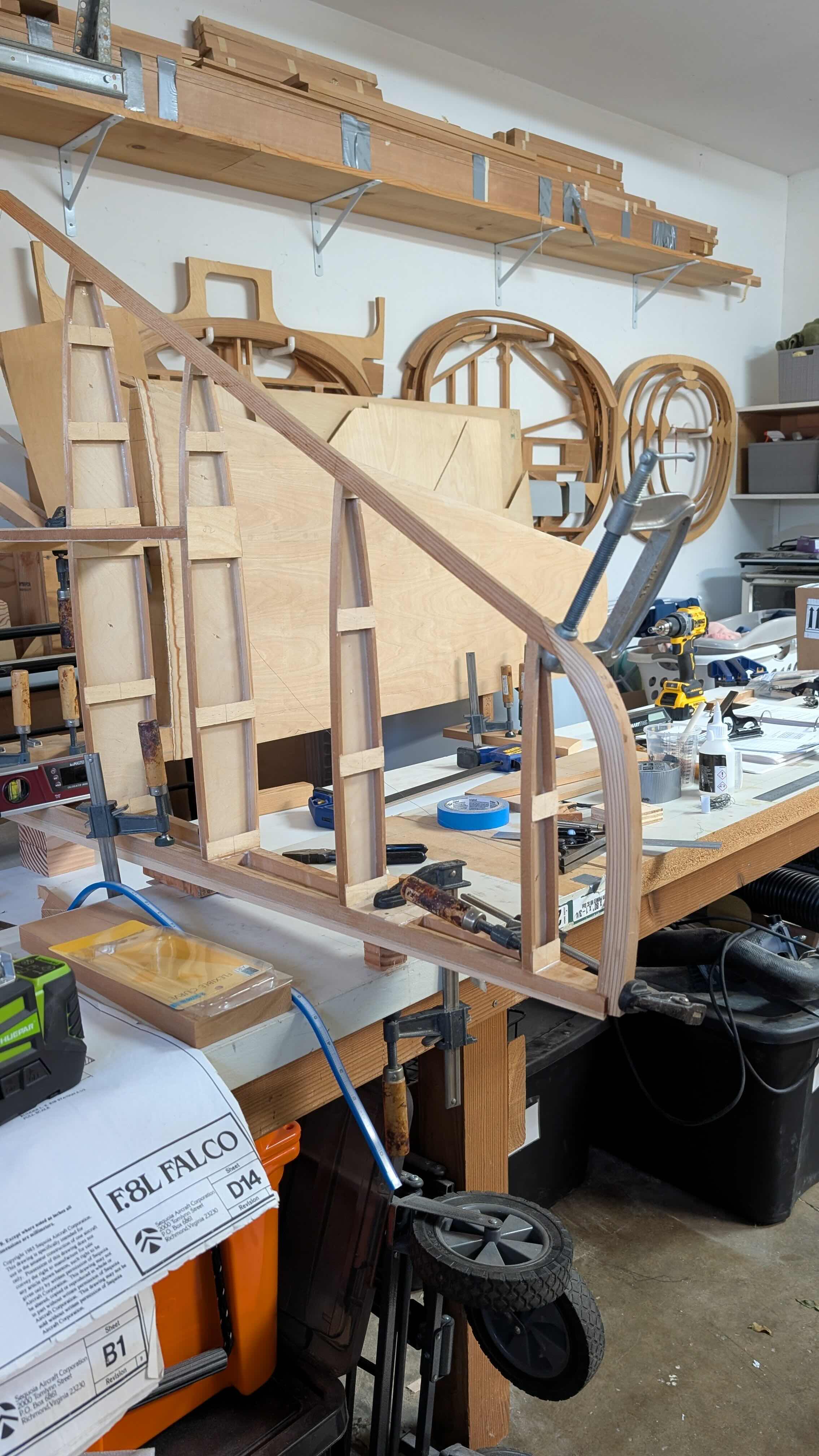
Here is the completed structure, removed from the jig. I had already started shaping the fin tip at this point.
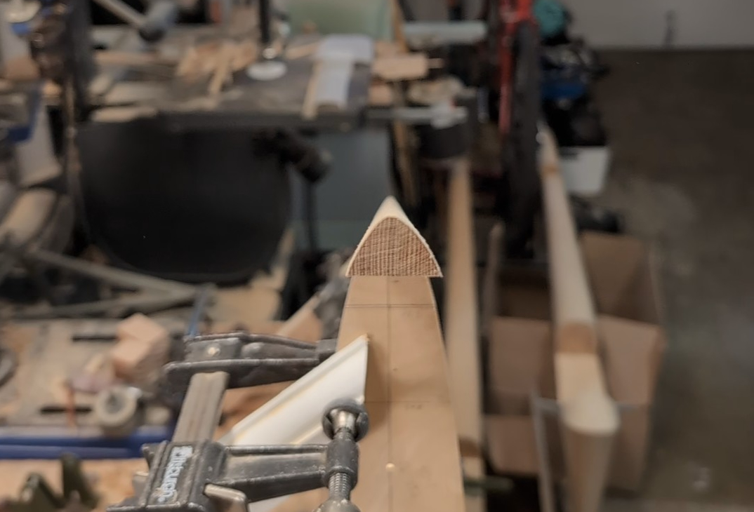
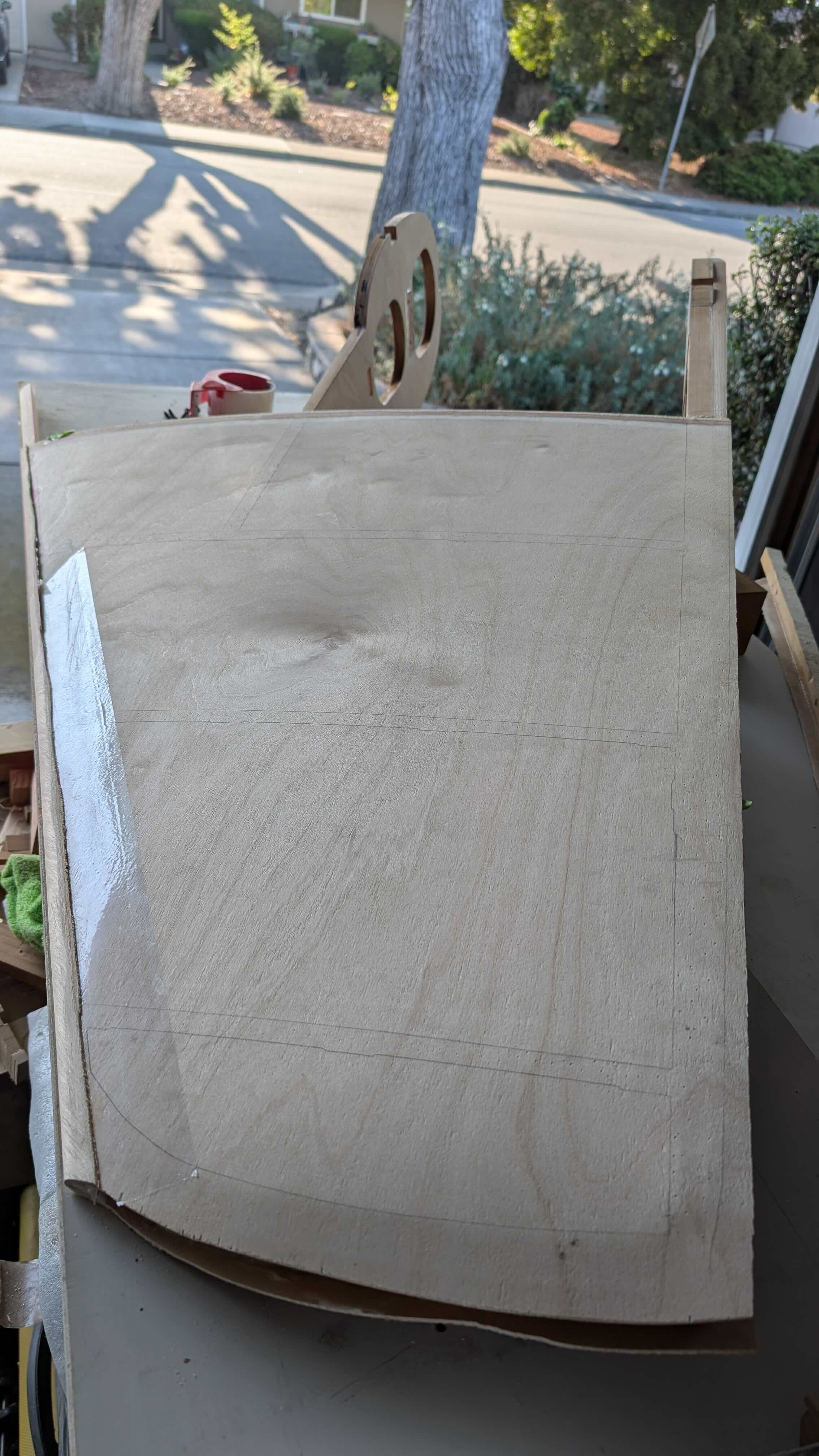
Float sanding was tedious but not tricky. The leading edge took a while but I used the shape of the cross-section at the bottom, transferred from the blueprints, and the pre-taper along the whole leading edge to guide me.
I prepped the skins, including adding the #1 VHF comm antenna to the inside of the right skin, varnishing underneath the antenna and the routing of the coax cable. I epoxied over the antenna to ensure it stays fastened to the skin. The right skin was glued on, then bent around the leading edge, followed by gluing that bend and feathering it to accept the left side skin.
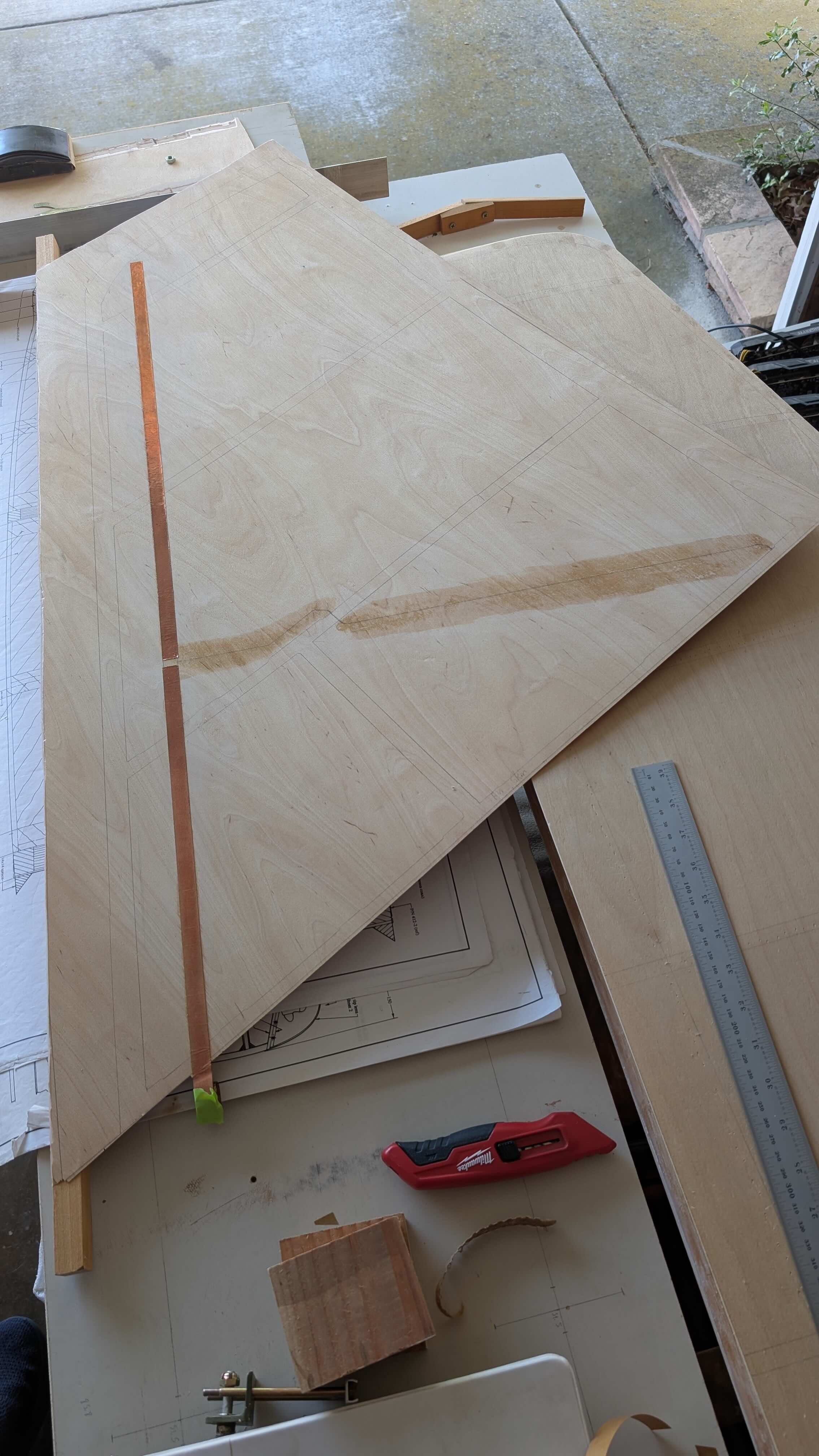
I soldered on the coax cable and installed the toroids for the balun, held down with heat shrink. The coax cable was temporarily held in its routing position with hot glue.
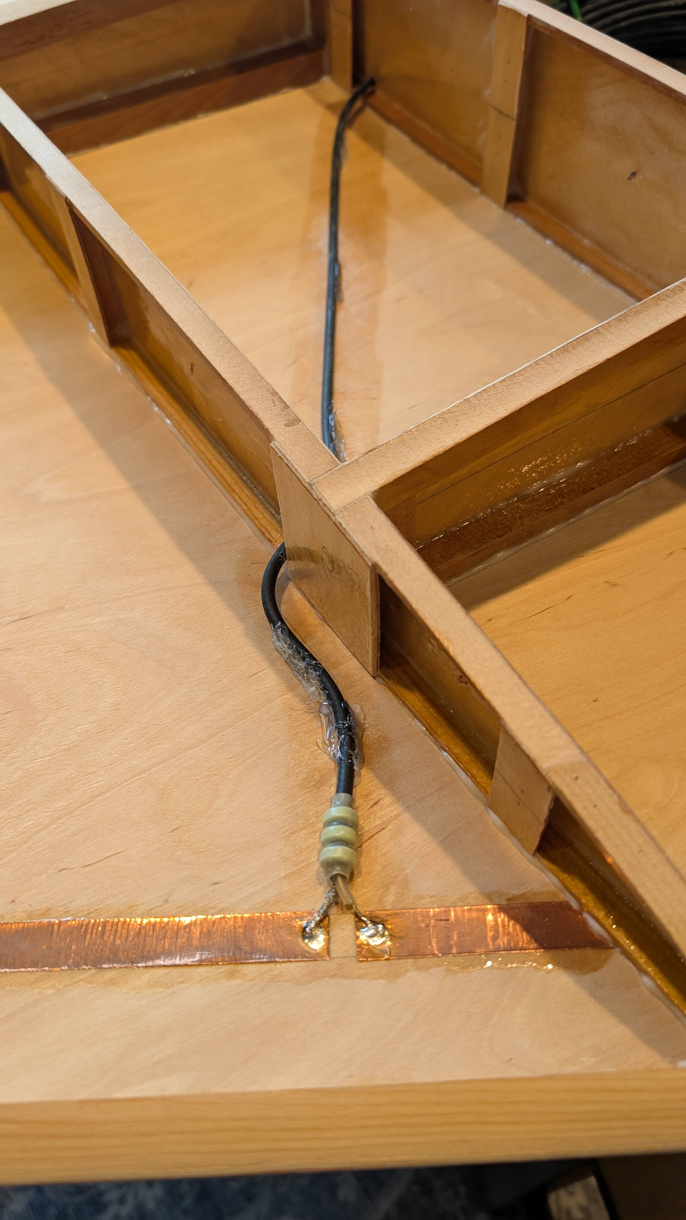
Final prep for closing the fin with the left skin included adding a strip of fiberglass to rigidly fix the solder joints and coax cable to the right hand skin and final varnishing of interior structures and left side skin.
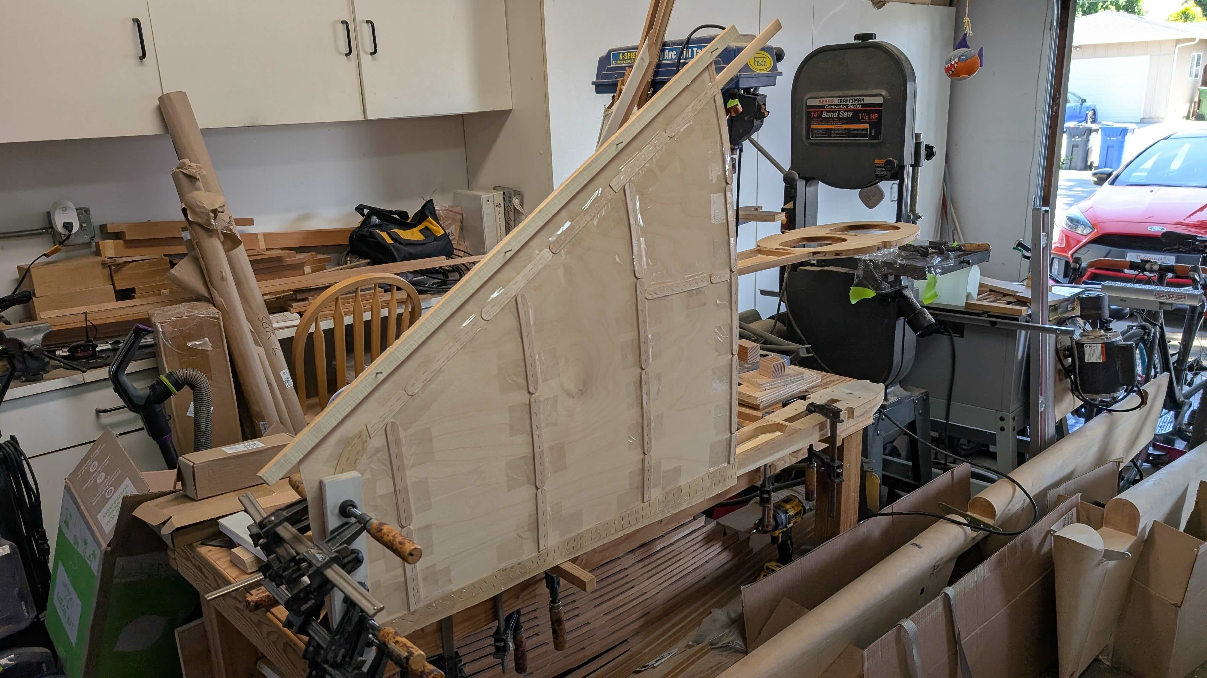
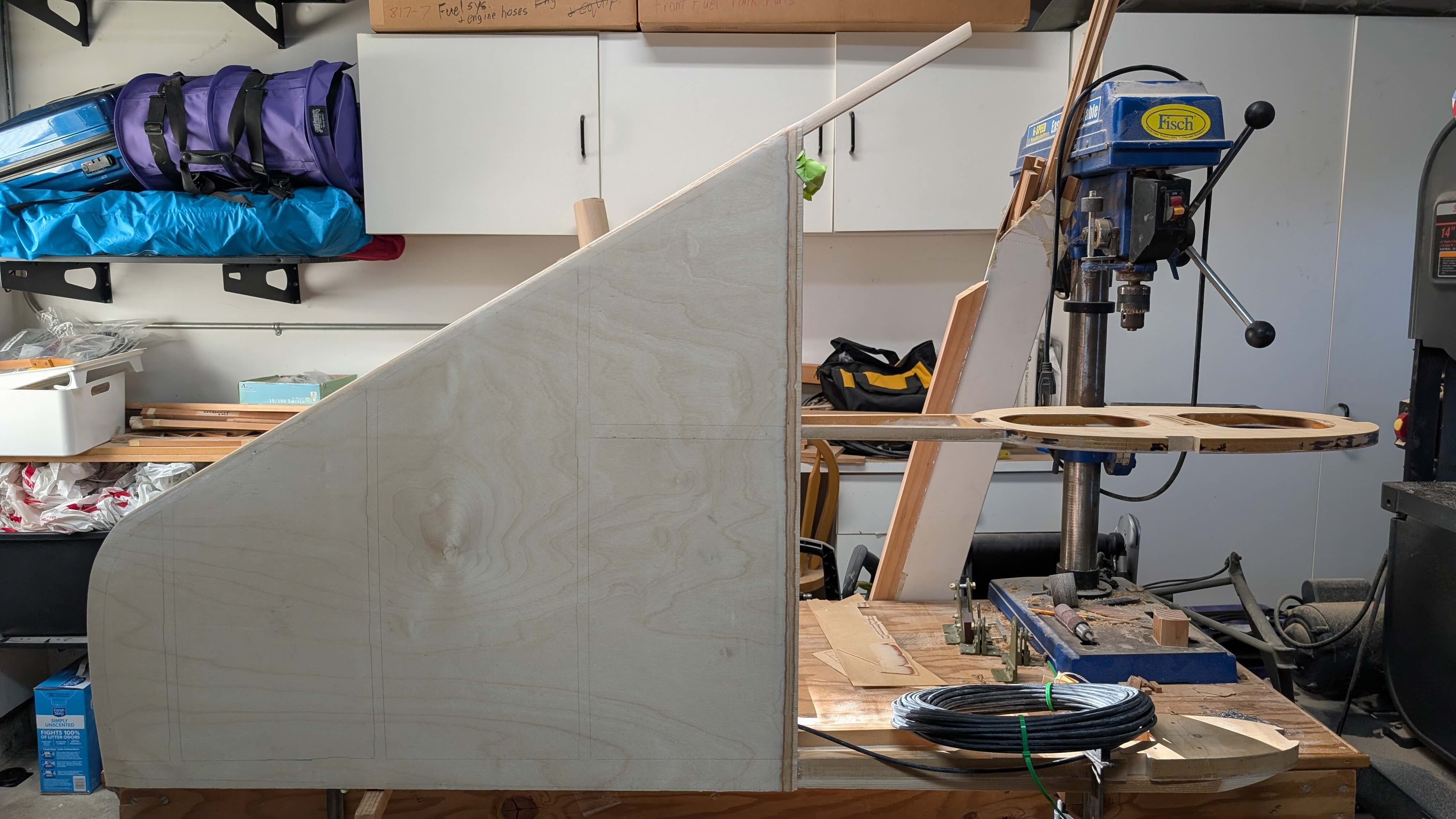
The left skin was glued on, bent around (picture is mid-bend) and trimmed, followed by sanding the leading edge round.

Here is the completed fin assembly.
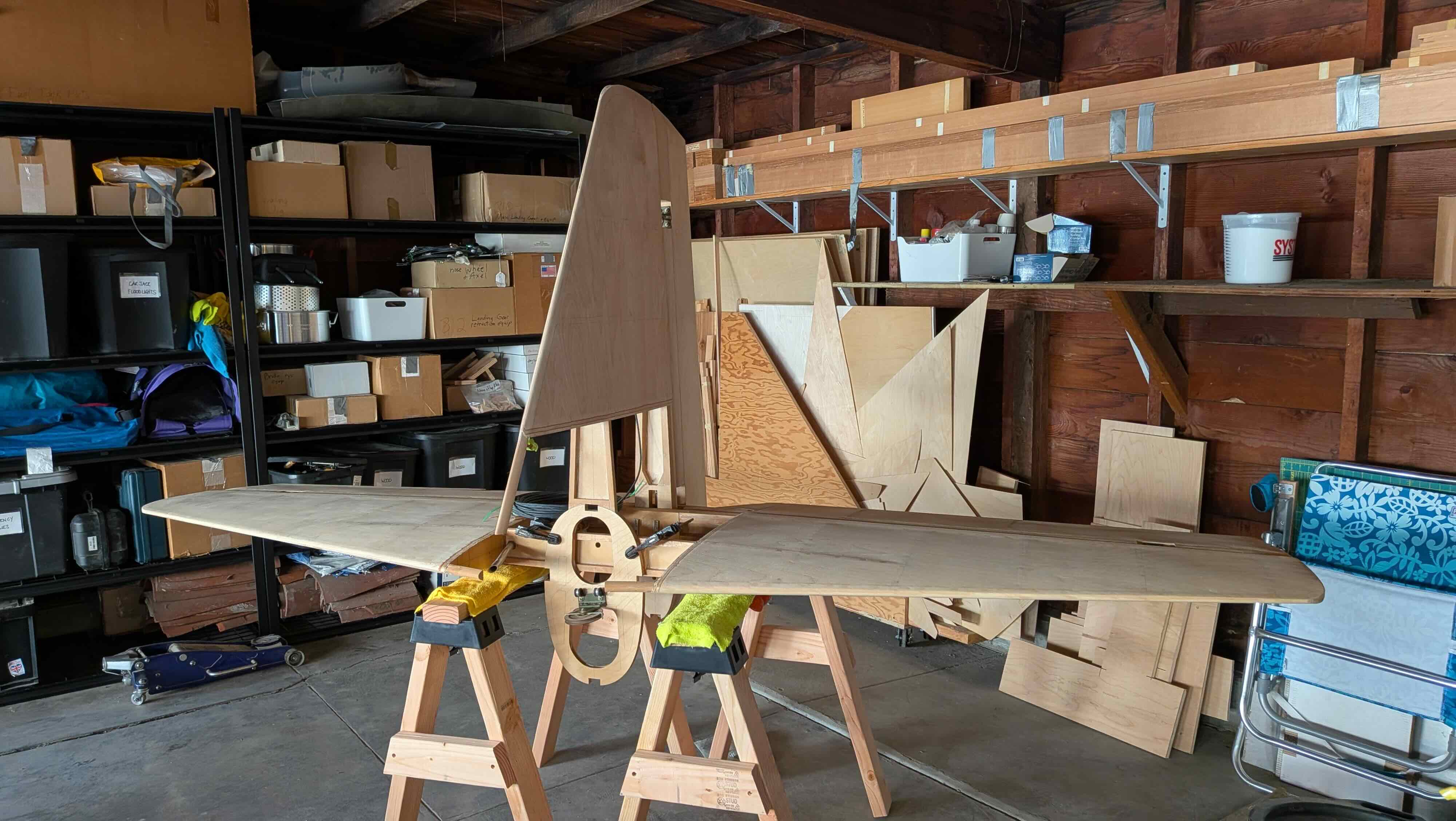
And with that, my empennage assembly is now complete! Well, that only took me 17 years (sigh). This picture is in the new garage! More on that in the next post. Onwards! I will be working on the ailerons/flaps next.
| Empennage Assembly Menu | Home